Design and construction of a RC tracked vehicle, partially autonomous
BASIC OVERVIEW
The project consisted of three main sub-projects:
- Mechanical design - the CAD project in SolidWorks and calculations;
- Electrical design - circuit design, PCB design and electrical calculations;
- Software design - developed an algorithm for radio-control and autonomous drive;
- Manufacturing - 3D printed and cut the PMMA plates (zap zap laser), etc.;
- Field tests - went outside to touch grass with it.
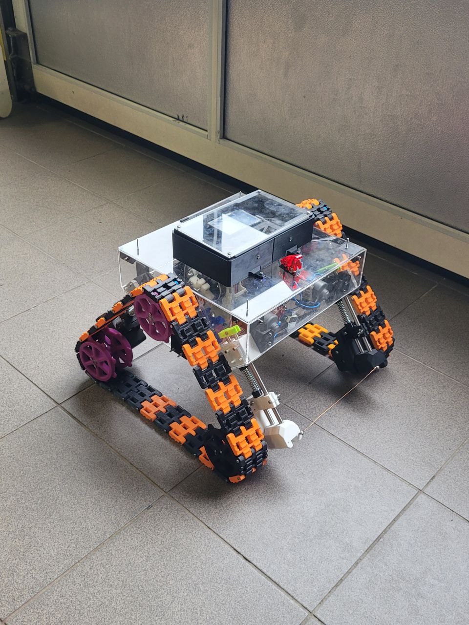
After all that a remotely controlled tracked vehicle made using 3D printing technology (Janusz V3) came to be. It features:
- A continuous track drive system with suspension springs, driven by two DC motors with worm gear drives;
- Radio control system using the FS-iA6b transceiver and remote;
- Autonomous system, using two ultrasound sensors and a RPi3 for data acquisition (makes maps);
- Transparent housing that allows the user to see the inner workings.
INTRO
Ever since I was a child, I was fascinated with radio-controlled vehicles and tracked vehicles. Somehow the technology to send signals from a remote to a machine, that moves according to my will was magical. The highest of the techs.
When I was in middle school, I got into Arduino with my friend Wrzosik. We made quite a team. I knew nothing about programming and electronics at the time, but I had The Vision, and Wrzosik had the expertise to make it happen.
We made our first RC vehicle, based on Arduino, radio module, brushed DC motors and some cardboard. We called it Janusz V1. Unfortunately, no photographic record survived. Later in high school we made a Janusz V2.
The V2 was a great success (I took it to my high school and convinced my physics teacher to pass me).
Years later, when it came to choosing topic for my engineering thesis, I have chosen to resurrect the Janusz project and make the V3, as I had The Vision and The Expertise now.
MECHANICAL DESIGN
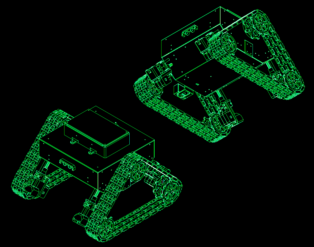
The mechanical design started with an idea of a rough shape that the robot should take. I considered unusual designs, like the ones of tanks from WW1. Drafted first design in CAD inspired by the Mark III British tank.
It looked unusual (as I wanted it) but seemed that it would not be practical in my application. I needed something that could “turn in place” easily. I figured that probably the best way to do it was to make it so the top view of my tank is roughly square… and the Mark III was more of a long rectangle.
I found inspiration in my father's old drawings of tanks, and WALEE (tbh I don't know what was the first thing that came to my mind), but this was the design I went with.
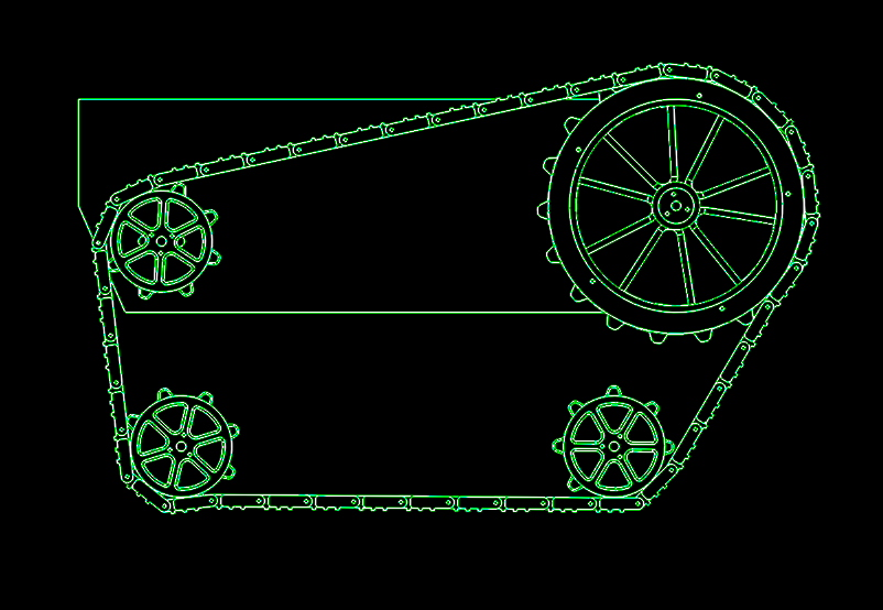
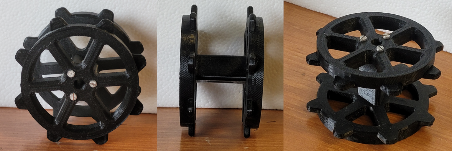
I simplified the track to a chain and the drive wheels to octagons. I have chosen to set the sides of the octagons to 40mm and this represented the distance between the axels in the real links. This allowed me to easily represent the dimensions for later design.
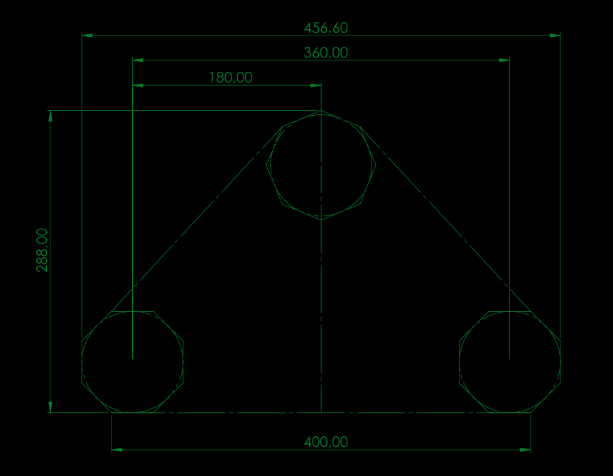
So, the drive wheels where also based on this octagon simplification. The outside octagon represents the track link – the side is 40 mm. The inside octagon is representing the bottom of the link [the sides are track_link_height / 2 away from the outside octagon].
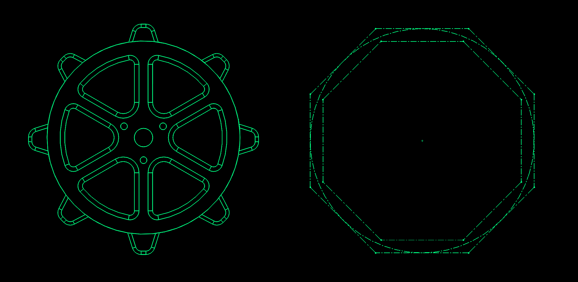
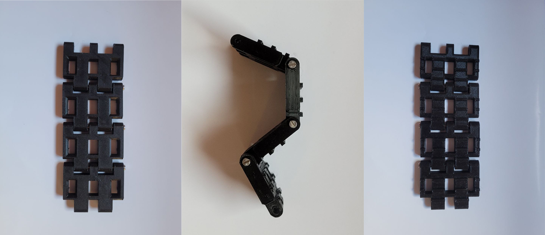
The track links where pretty straight forward. The mounting axels where made 40 mm apart. The holes inside the tracks where put in the center of the track. Two of them gripped the wheel and the center one was for material reduction.
NOTE: The third hole did not reduce the weight, bcs a 3d-printed part filling is less dense than extra four walls that I created making this hole ):<
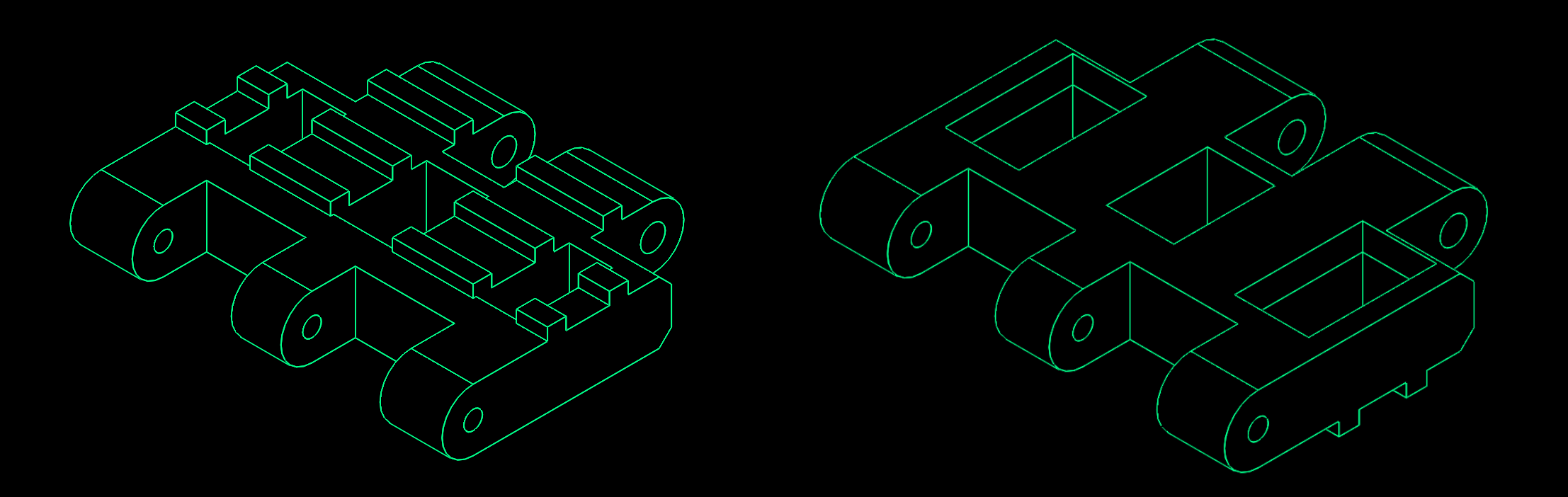
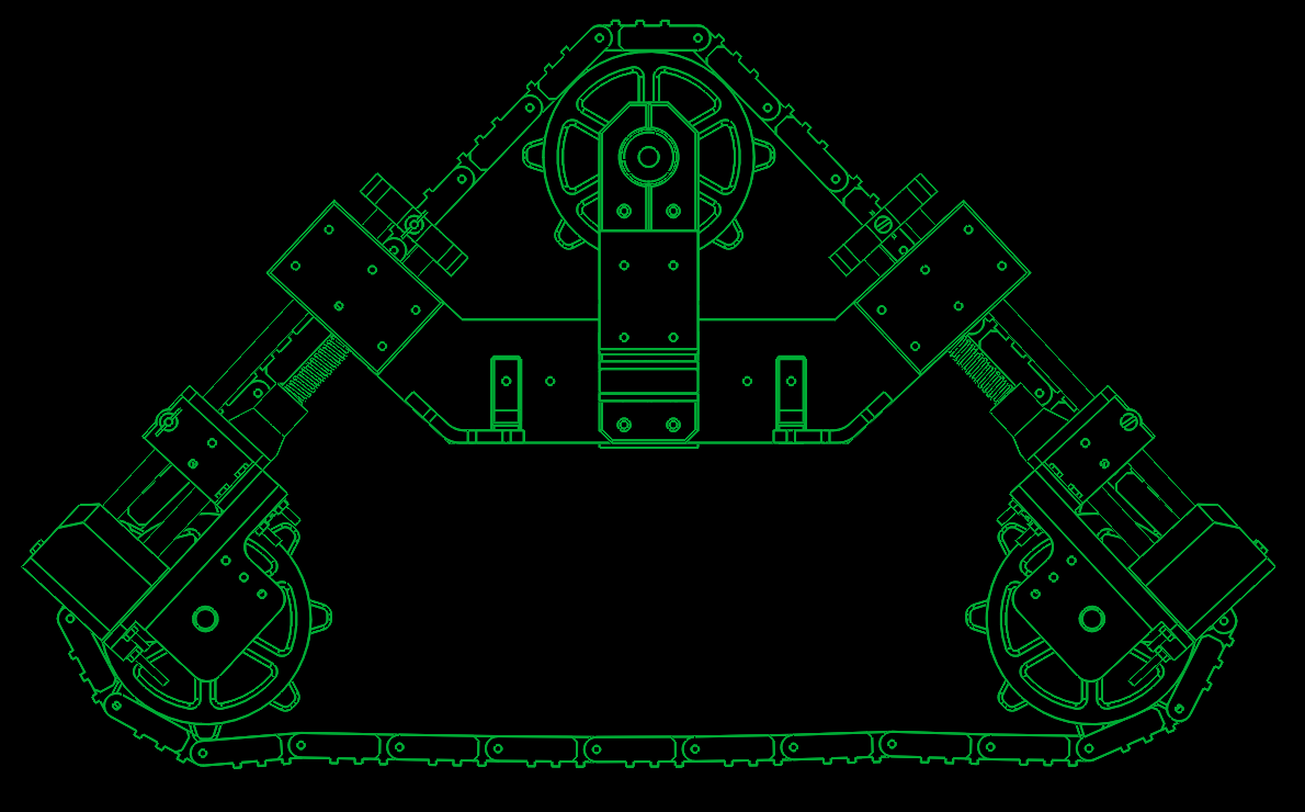
So assembling the whole drive system it looks somewhat like this:

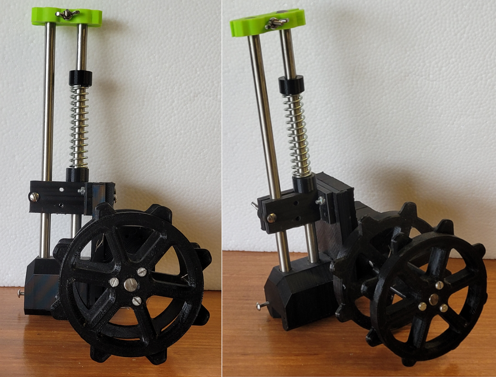
After designing that I started to work on the suspension system, which would also have to tension the track. The track needs to be constantly tensioned so it won’t slip on the drive wheels. I came up with a design that should take of these two challenges at once.
The holding system for the wheels is connected to the housing by two linear bearings, that allow it to slide up and down. Under the bearing housing I installed a spring that creates tension if the holder tries to move upward, therefore creating a constant tension on the track. It also amortizes the vehicle.
Two of these holders were installed on each side of the vehicle. The top wheel was secured with a bearing.
In the lower part of this part is bearing housing for the wheel axis. I made calculation of how heavy my tank can be, based on the maximum bearing load. When it came to the rolling bearings – 1117 kg (unobtainable amount of mass XD), and the linear bearings – 452 kg (also a lil bit bigger that I think I can manage with 3d-printers).
The shaft is secured with a ring with a screw tightener and two bigger, slimmer rings inside the bearing housing.

Now that I finished the suspension system, I started to work on the clutch connecting the motors to the tracks. Because I needed to do it cheaply, I bought DC motors from WOLTZWAGEN. The motors were used to drive the windows up and down, so they already had the worm gear installed. Unfortunately, the motor axis had an unusual connector which made it hard to couple with the main drive shaft.
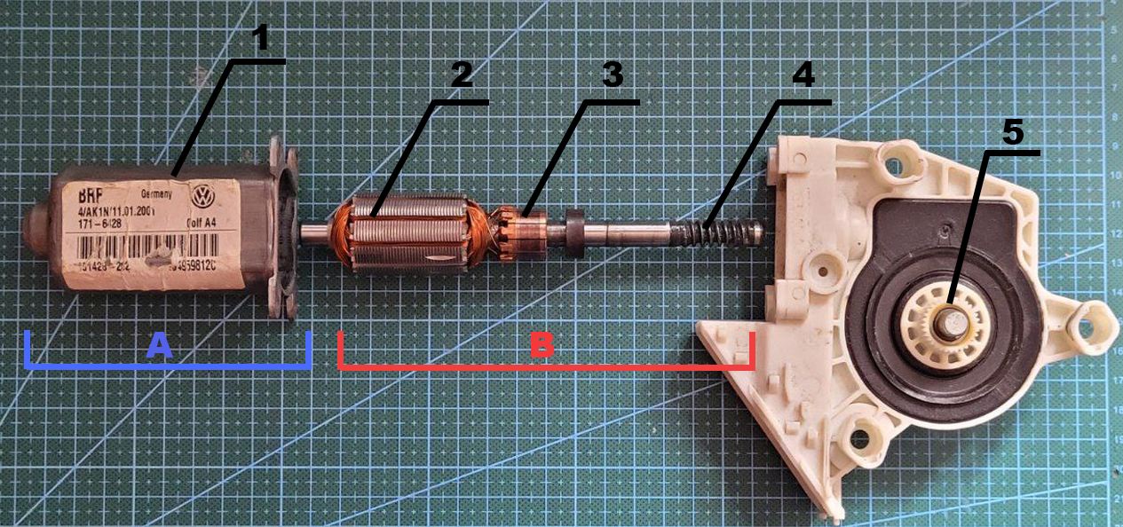 1-Motor housing;
2-coils;
3-commutator;
4-worm gear;
5-motor shaft.
1-Motor housing;
2-coils;
3-commutator;
4-worm gear;
5-motor shaft.
Shafts are 8mm (tracks) and 16mm (motor) in diameter. With these dimensions buying an existing clutch would be too expensive for me at the time. I designed a permanently engaged clutch that connected to the shafts via friction. On each side the clutch has two jaws that squeeze on the shaft. Jaws are tensioned by a pair of M3 screws. The two sets of jaws also connect via M3s.
NOTE: In testing the robot, I found out that was the worst part of my design, as the clutches tended to be unreliable in the long run. I had to glue them to the shafts so they don’t disengage randomly. I recommend just using a keyway connection or just buying the commercially available clutches.

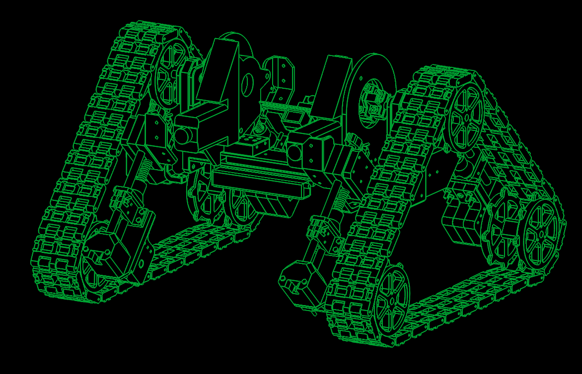
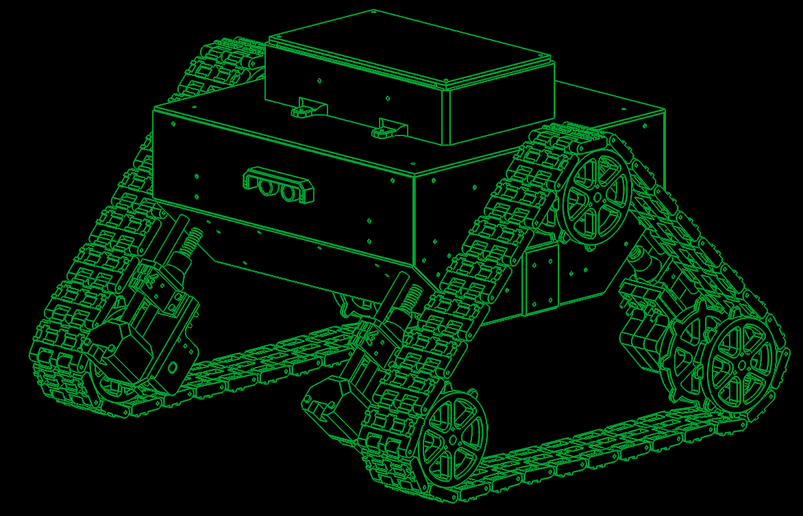
Last part of the CAD design was to make a housing for that big boi. To be honest here I was just designing it as simple as I could. I didn’t want to spend a lot of money on the materials so I just designed a PMMA box that fitted my requirements.
 |
|| \/
AND NOW...
Aerodynamics of a robot:

Aerodynamics of a robot
ELECTRICAL DESIGN & SOFTWARE
In this part of the project firstly I had to select components for my vehicle. It felt like a putting together a puzzle. ESP32 would be nice, but it was 3.3V and all the other components where 5V. I could have used a voltage level shifter but thought of it as unnecessarily complicated at the time (I was wrong). At the end I used Arduino Nano as a main controller of the vehicle, and Raspberry Pi as a HMI system.
This is a list of the electrical components:
- Arduino Nano
Controlling the motor driver, reading PWM from radio receiver and impulse signals from ultrasonic sensors, I2C communication with magnetometer - Raspberry Pi 3 B+ & LCD screen
Drawing the map for the autonomous drive, sharing the map files (via a file server, on its WiFi network), showing the files on LCD - FS-iA6B
Radio signal receiver, sends signals via PWM channels - IBT-2
DC motors driver, drives motors (duh) - HC-SR04
Ultrasonic distance sensor for wall detection - DC motors
DC motors from an old Volkswagen Passat (window control) - QMC5883L
Magnetometer (digital compass) - XY-3606
Voltage stabilizer (5V) - LiPo 11.1V
LiPo battery (1.2Ah) with an undercharge alarm - PCB
A PCB I made to connect all the components together - Other small parts
Resistors, diodes ...
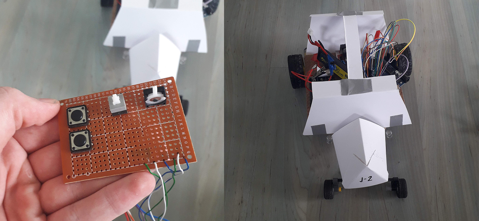
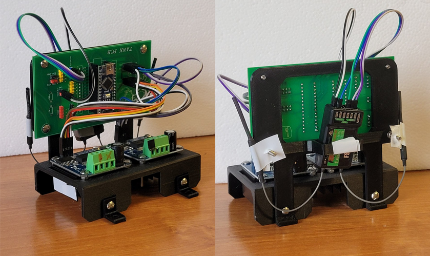
Firstly I started working on a PCB schematic to simplify the spaghetti of tangled wires I created while prototyping. I never did this before so I had to learn the EDA software. I have chosen KiCAD because it was free and its UI looked understandable to me.
This is the schematic I came up with for the PCB:
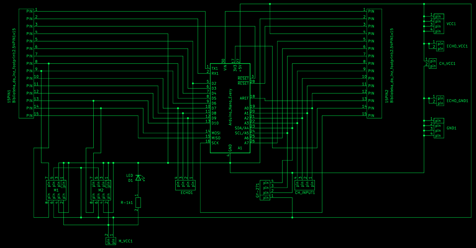
It has two 15-pin headers so I can access any pin from the Arduino Nano, that’s in the center. On the lower left side you can see plugs for the motor driver control and a LED to indicate that the system is turned ON. On the right there are plugs for the power_in, sensor_in, i2c and radio connection.
So I made a PCB based on it:
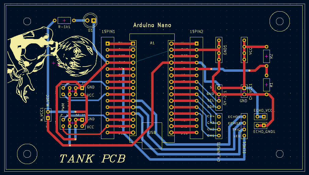
Trust me, that Rei is essential to the workings of the board.
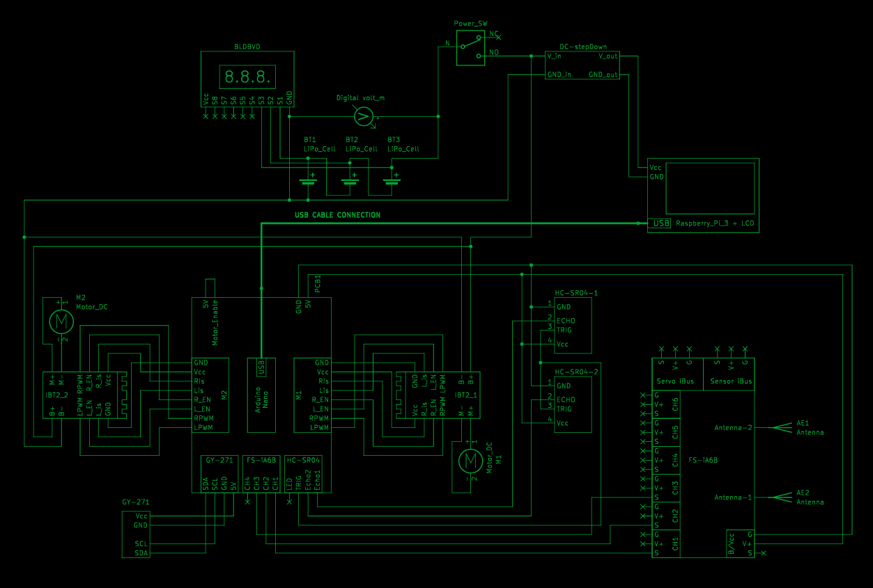
Afterwards I made the circuit depicting the whole electrical system of the vehicle. On the top of the schematic there is a LiPo battery with a alarm system, switch and a voltage stabilizer module (to 5V). Raw voltage from the battery is fed directly to the motors via the drivers, and the rest is powered by that 5V. On the bottom there is a PCB with all the sensors and radio.
MANUFACTURING
I made the parts using 3d-printers and a laser cutter provided by my university.
I used ENDER 3’s and PRUSA K1’s for the 3d printing. All of the parts where printed in PLA, because the uni didn’t want to use ABS (it can be toxic to ppl when printing).
PLA isn’t a bad material, but it has it’s issues. For example it will significantly soften when heated to ~60°C. Some of the mechanical parts can heat up over time to that temperature, so ABS would be a better fit for my project – but hell, peoples health is more important and I won’t argue with that!
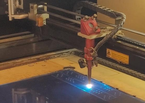
The laser was used to cut the PMMA (plexiglass) sheets. Not much to say about that, besides that it smelled weird af. Laser be cutting. Here photo of laser cutting. Smurt laser :P
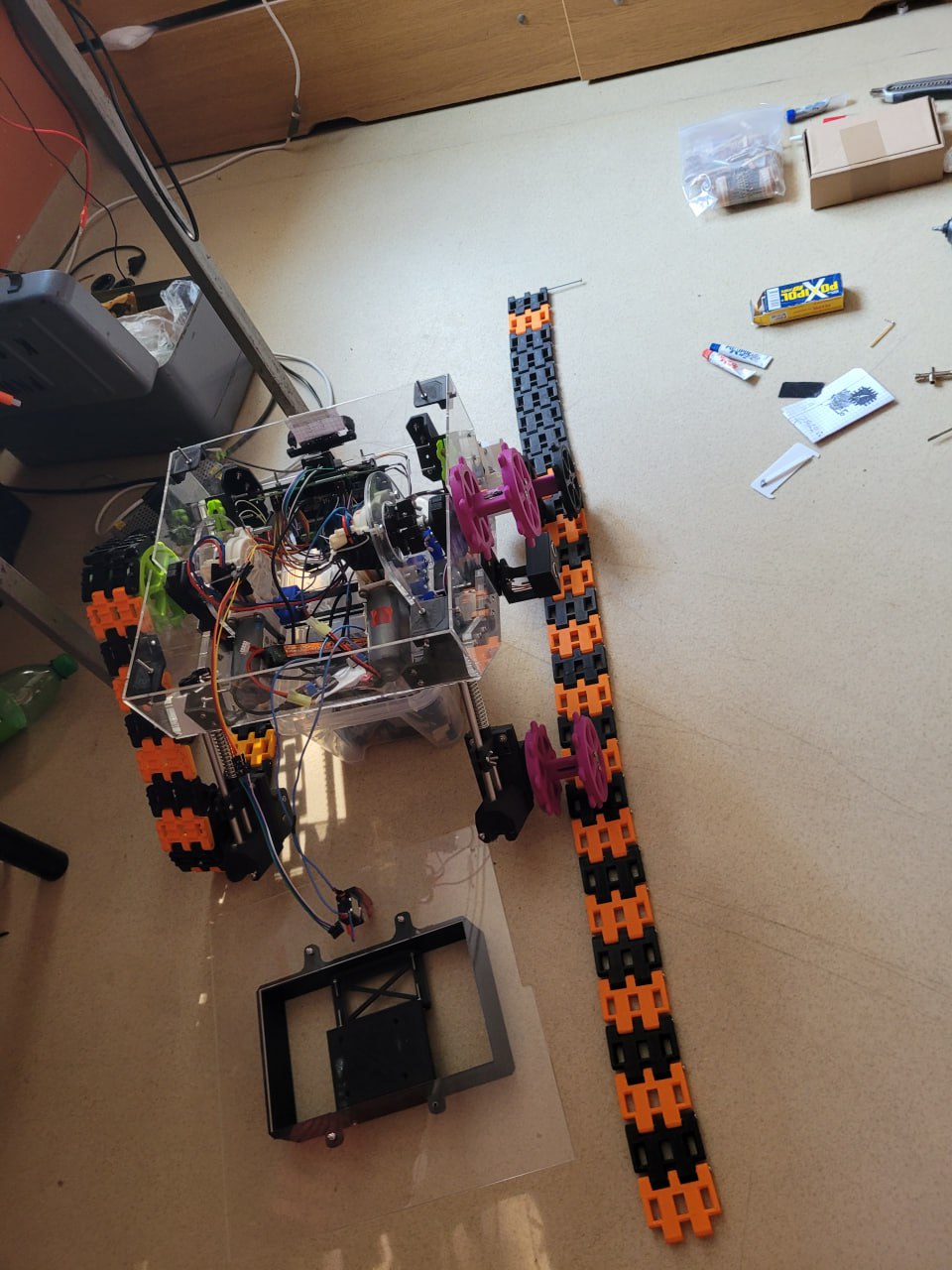
ASSEMBLY
First I assembled the wheels and tracks. There where no significant issues with that, besides the fact, that the wheels shaft holes where too tight and needed to be re-drilled (my shaft was ⌀8mm and the holes where ~⌀7.8 mm).
Then I made the suspension system. Springs and bearings fitted nicely, no issues there.
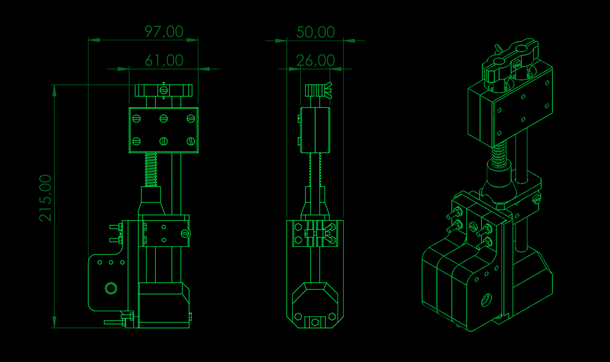
I also assembled the electronics holders. I like how they look :3
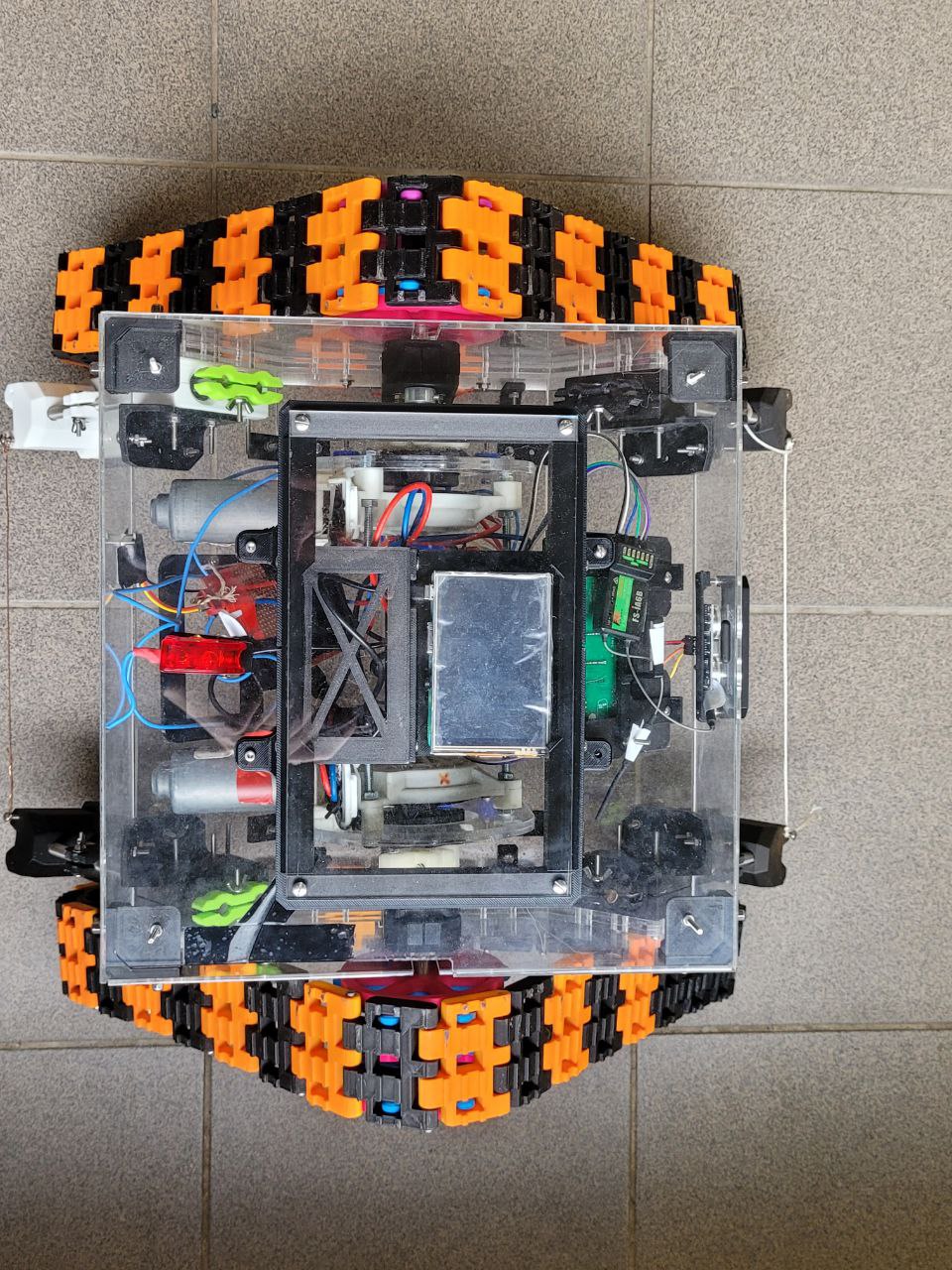
Having done all that I printed the rest of the small connectors for my robot’s housing, and started assembling it.
FIELD TESTS
So, after making the big guy I had to test it. I wrote some code for the Arduino and Raspberry and added a simple file server so I can download the map files easily from the robot.
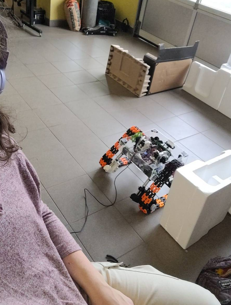
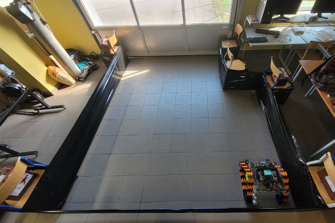
To test the mapping-autonomous drive system, I made a small, simple track out of some stuff laying around my professor’s workshop. It had right and left turns, so I could test both possible scenarios. Later I made a bigger one, from chairs and foil XD
The testing showed me that my algorithm was kinda dumb and needed a lot of tweaking. Mainly I had issues with the ultrasonic sensors. They love to give really dumb reading sometimes, or saying it more professionally: shit is prone to noise and false readings. The effect of that was that occasionally, the robot just turned randomly, even though there was no wall in front of it.
My solution to that was:
- Average the shit out of these readings: take 25 and average it;
- Check twice: when robot would “detect” an object, I would make it go for another 0.25s and take the reading again.
This seemed to fix the shitty sensor issue.
Other problem I had was with the magnetometer. The robot makes 90° turns based on its readings, BUT if the readings are shitty, the turns are just random. Sometimes it would turn endlessly, stuck like ants stuck in an ant mill, doomed to drain the battery and die (st00pid).
This happened because the workshop I was at had a lot of high power electronic equipment, and it created LOTS of magnetic noise. When I went outside and tested the turning, everything seemed fine.
I did not find a good fix for that, besides using timed turning or changing to a different type of sensor. At the end, I used the timed turning inside the workshop. It worked good enough. I also added a simple function that would correct the robots path, if it would get too close or too far away from the wall.
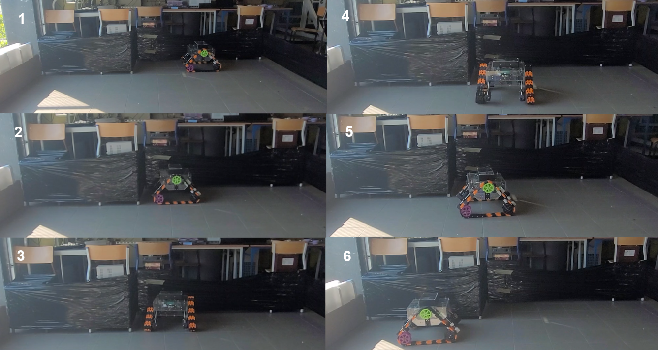 Photo sequence of how the robot drives in auto mode.
So, with these issues delt with, it worked. Mapped the track well and detected all the walls :3
To check the manual drive part, I just took it outside to touch some grass, as the guy was a basement dweller ever since it was assembled :P
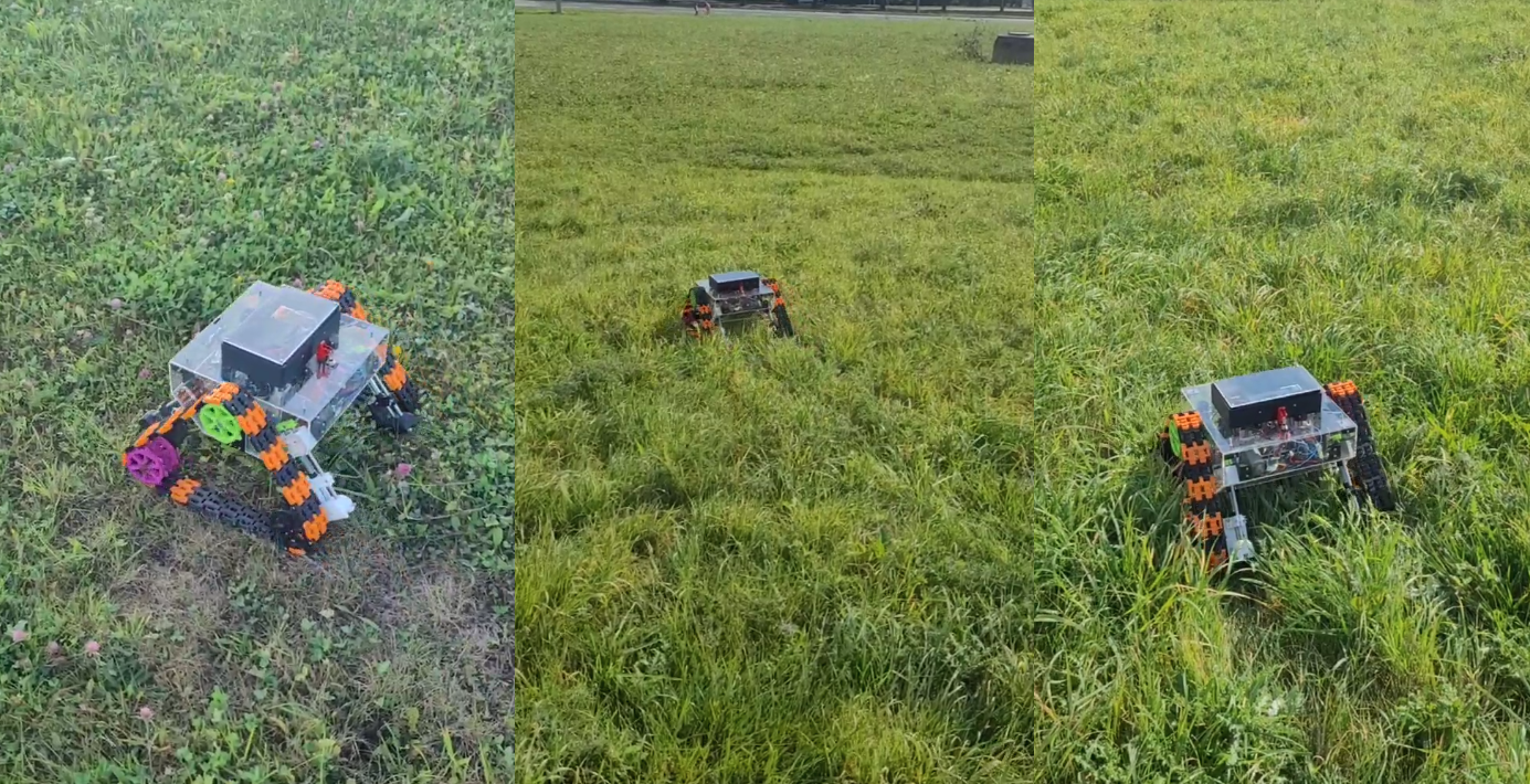 The robot in its natural environment.
I think it liked the grass :3